
- Overview
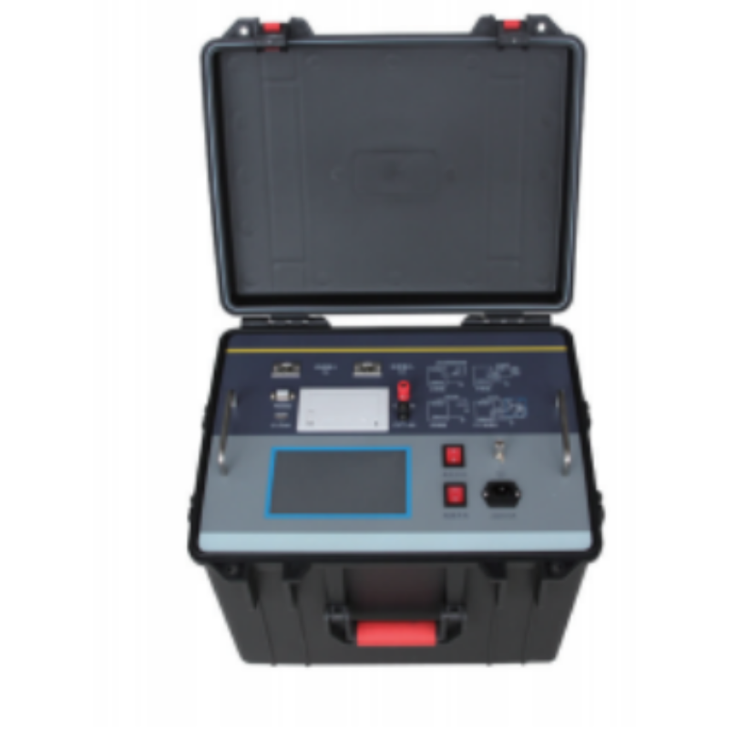
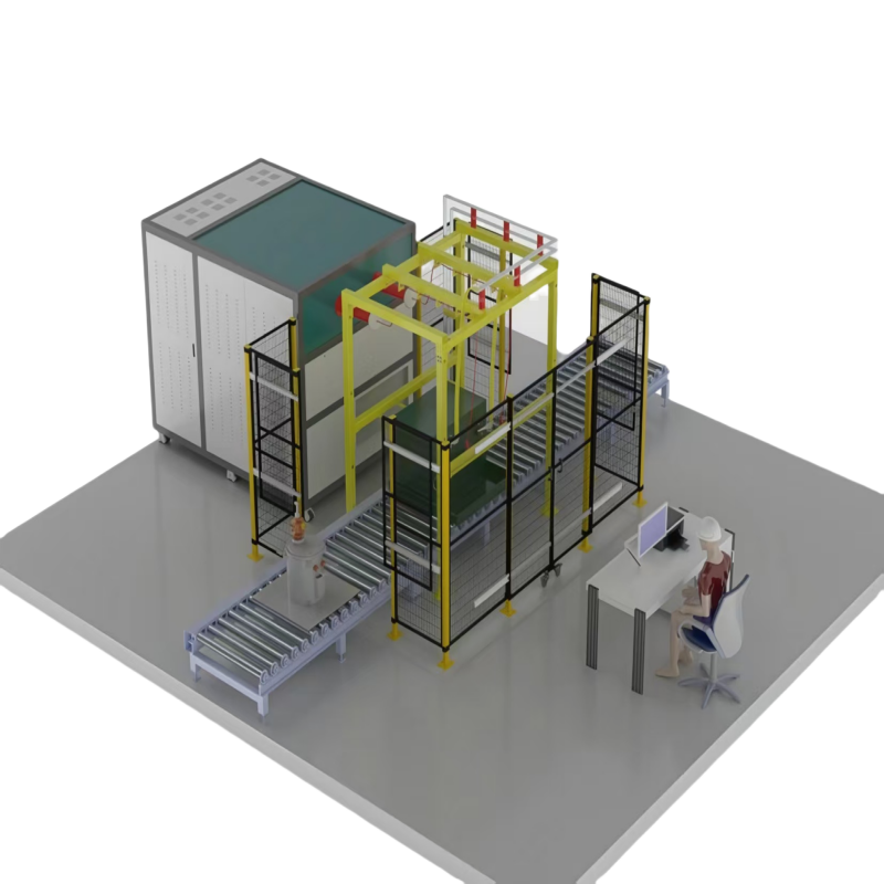
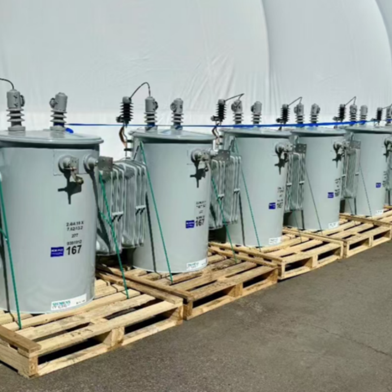
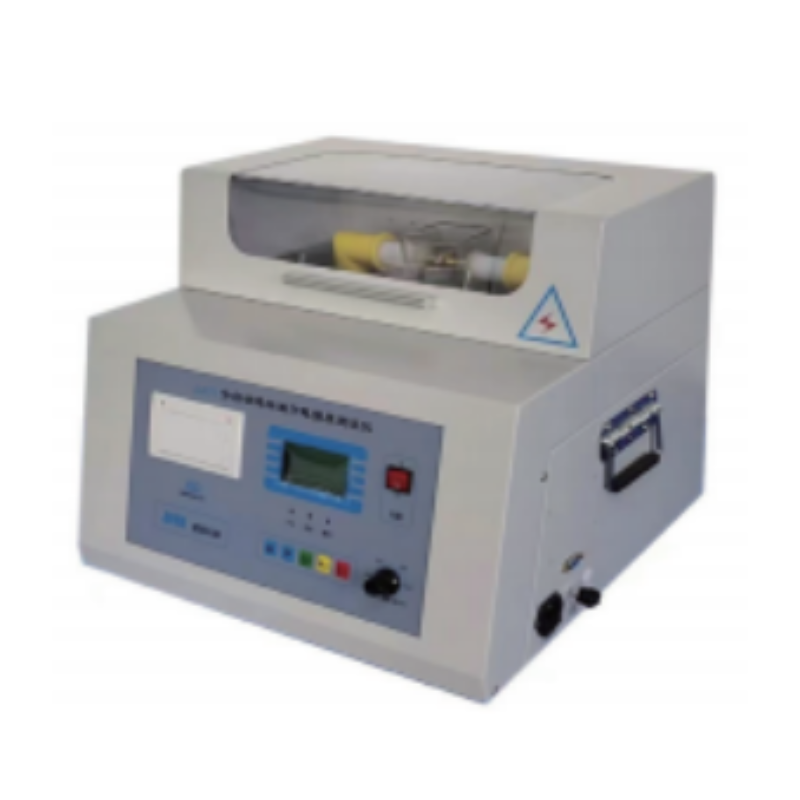
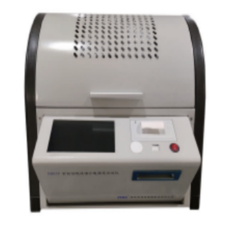
- Recommended Products
- Manual/Automatic Charging Mode: Manually adjust the charging voltage.
- Synchro with the set charging voltage of the ball gap to manually adjust the gap distance, and display the actual distance value.
- Charging speed selection: Users can select two charging speeds based on test needs.
- A standardized waveform editing system allows waveform measurement by dragging and dropping with the mouse, and waveforms can be easily zoomed in and out.
- Overvoltage and overcurrent protection, with automatic grounding.
- Automatic ignition: Manually controlled.
- Emergency trip: Unlike manual trip, the emergency trip directly cuts off the main circuit power supply at the push of a button. This is used in emergency situations, such as control room power outages.
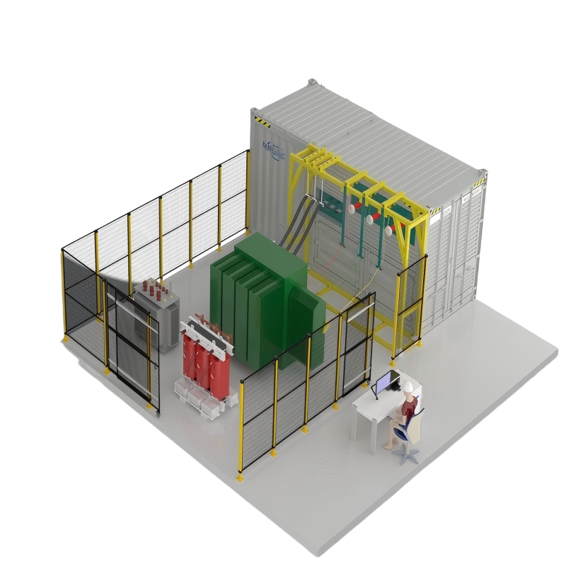
Scope of Application
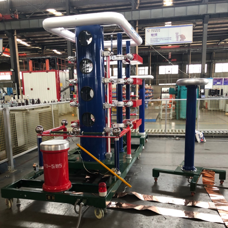
This impulse voltage generator test system is primarily suitable for full-wave lightning impulse voltage testing of power products 35kV and below. It can also be used for impulse testing of other products.
General Operating Conditions
Altitude: 1000m
Ambient Temperature: -5°C to +40°C
Relative Humidity: 90%
Maximum Daily Temperature Range: 25°C
Operation Environment: Indoor
Free of conductive dust
No fire or explosion hazard
No gases corrosive to metals or insulation
The power supply voltage waveform must be a true sine wave with a waveform distortion rate of <5%
Compliance Standards
GB/T 311.1 Insulation and Coordination of High-Voltage Transmission and Transformation Equipment
GB/T 16927.1 High-Voltage Test Technology - Part 1 - General Test Requirements
GB/T 16927.2 High-Voltage Test Technology - Part 2 - Measurement Systems
GB/T 16896.1 Digital Recorder for High-Voltage Impulse Tests
JB/T 7616 Steep Wave Impulse Withstand Test for High-Voltage Line Insulators
DL/T 557 Steep Wave Impulse Test for High-Voltage Line Insulators: Definitions, Test Methods, and Criteria
BF 24001 Impulse Voltage Test Implementation Details
Rated Parameter Values
1. Nominal voltage: 400kV
2. Rated step voltage: 100kV
3. Total impulse capacitance: 0.25 microfarad (single pulse capacitor 2 microfarad/50 kV, 8 units in total).
4. Total number of steps: 4 steps
5. Standard waveform parameters:
Standard lightning impulse voltage full wave, 1.2/50s voltage utilization factor >85% (greater than 90% at no-load 300PF);
Impact voltage waveform parameters and their deviations meet the requirements of relevant national standards GB311 and GB16927.
6. Minimum output voltage greater than 10% of nominal voltage
7. Duration of use: Above 70% of rated voltage, continuous operation can be achieved with charge and discharge every 120 seconds; below 70% of rated voltage, continuous operation can be achieved with charge and discharge every 60 seconds.
Main components
1. Charging part
(1) Constant current charging device is used;
(2) Oil-immersed charging transformer is used, secondary voltage is 85kV, rated capacity is 5kVA;
(3) 2DL-200kV/200mA high voltage rectifier silicon stack is used, reverse withstand voltage is 200kV, average current is 0.2A, high voltage rectifier silicon stack is installed next to the charging transformer, and the charging voltage polarity can be automatically reversed by the transmission mechanism. There is a polarity switch button on the console;
(4) The high voltage rectifier silicon stack protection resistor uses enameled resistance wire with inductive winding on the insulating tube;
(5) Bilateral symmetrical constant current charging method is used;
(6) During automatic control, the constant current charging device shall have a deviation of no more than ±1% from the set voltage within the range of 10% to 100% of the rated charging voltage, and the instability of the charging voltage shall be no more than ±1%. The adjustable accuracy of the charging voltage shall be 1%;
(7) Two DC resistor dividers shall be used, using 50kV, 300M, oil-immersed metal film resistors. The low-voltage arm resistor shall be installed in the bottom flange of the divider, and the voltage signal on the low-voltage arm shall be introduced into the control console using a shielded cable;
(8) The automatic grounding switch shall use an electromagnet grounding mechanism, which can automatically short-circuit the main capacitor and ground it through the protective resistor when the test is stopped;
(9) The constant current charging inductor, capacitor, charging transformer (including high voltage rectifier silicon stack and polarity conversion device) and its protective resistor, automatic grounding switch and insulating support are installed on a chassis;
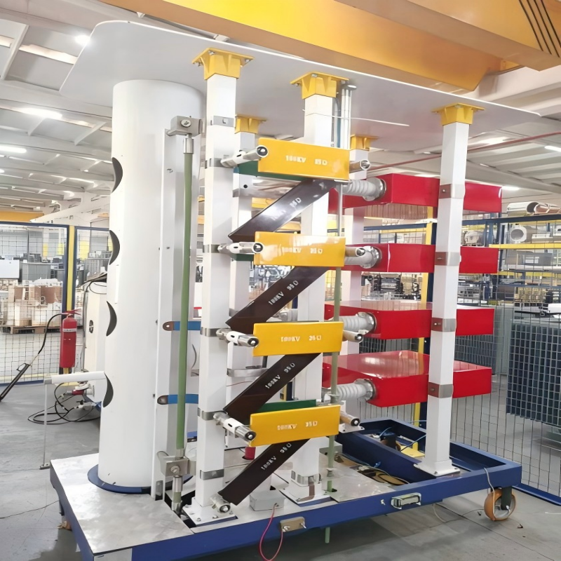
2. Main body
(1) The main structure adopts a four-column structure, with a steel frame consisting of four flanges and two capacitors mounted in parallel, forming a stable structure consisting of one level. The main equipment is four levels, forming a combined tower structure, each level is stacked step by step, easy to disassemble and inspect, and the overall structure is stable;
(2) The main body adopts an asymmetric constant current charging method, constant current voltage regulation, continuously adjustable from zero to set voltage, and automatic shutdown of the charging power supply at the moment of ignition discharge. The rated voltage of each level is 100kV;
(3) The main body insulating support has a four-level tower structure. Each level includes two MWF50-0.6 iron shell oil-immersed pulse capacitors, charging resistors, wave head resistors, wave tail resistors and ignition ball gaps, etc. All synchronous discharge balls are installed in a closed insulation, and the ball gap can be manually or automatically adjusted through the control console.
(4) The single pulse capacitor is 2.00.05F, the DC working voltage is 50kV, the capacitor inductance is 0.2H, and the composite film oil-immersed insulation is used. Under normal working conditions and working environment, the capacitor outlet bushing can withstand a vertical pull of 15kg, while ensuring that it will not be damaged or leak oil;
(5) The wave head (front) resistor and the wave tail resistor are both plate-shaped and wound without inductance. Their self-inductance is 2.5H (the purpose of reducing inductance is to increase the load capacity. For extremely large loads (such as more than 5000PF), this can be achieved by using a suitable combination of external modulation capacitors and modulation resistors to increase the load.). The connectors are all spring-loaded;
(6) The wave head (front) and wave tail resistor brackets can be connected in parallel by four resistors at the same time. The wave head (front) and wave tail resistors are of equal length and can be used universally. Each level is equipped with a position for storing excess modulation resistors and short-circuit rods. The generator can be easily operated in series by plugging in the short-circuit rods;
(7) The complete set is equipped with
7.1 2 sets of lightning wave head resistors;
7.2 2 sets of wave tail resistors;
7.3 1 set of charging resistors (1 spare);
(8) The first-stage ball gap adopts bilateral polarity triggering, and the second to fourth-stage ball gaps all adopt three-gap ball gap ignition. The synchronous misoperation rate or rejection rate is not greater than 2%; the synchronization range is ≥20%.
(9) The distance between each ball gap is linearly adjusted by the motor drive. The control system indicates the charging voltage corresponding to the ball distance. The transmission structure has upper and lower limit switches;
(10) The ball gap distance can be adjusted manually or automatically on the control system;
(11) The main body can be used in parallel for two or three stages. The parallel connecting rod adopts a unified connector for easy replacement. The equipment can place extra wave modulation resistors without affecting the electrical performance;
(12) Each stage test has a bracket for storing wave modulation resistors and connecting rods;
(13) Each stage adopts a two-end sealed insulation tube with good sealing performance;
(14) Anti-corona measures are taken between each stage. No obvious corona will appear during the entire charging process.
(15) The inter-stage insulation and mechanical support can withstand 100kV DC voltage without generating discharge.
(16) A voltage equalizing cover is installed on the top of the generator.
3. 400KV weak damping capacitor voltage divider
The high-voltage arm capacitor consists of 1 section, with rated parameters of 400kV/600 pF and rated lightning impulse withstand voltage of 400kV. The voltage divider is equipped with a low-voltage arm capacitor, with a voltage division ratio of 1000 and a voltage division ratio accuracy of less than ±1%;
Impulse voltage generator control and computer waveform analysis system
1.Overview
2. Main functions of the control system: control and computer measurement.
3. System Structure
The system structure diagram is shown in Figure 2:
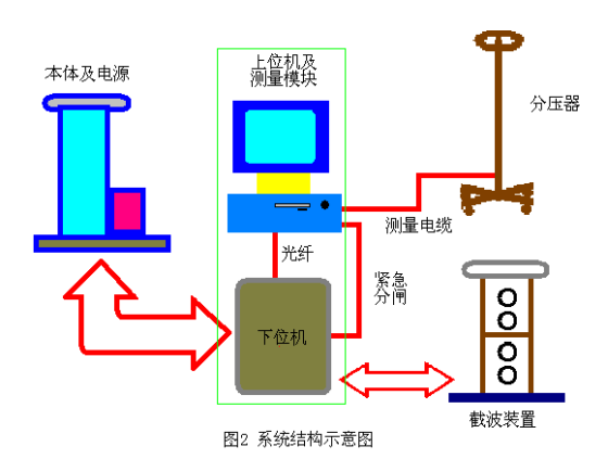
The area surrounded by the green line in Figure 2 represents the integrated measurement and control system. The lower computer is directly connected to the impulse voltage generator, power supply, and chopper. All low-level operations, such as relay opening and closing, are controlled by the lower computer. The upper computer is connected to the lower computer via optical fiber and sends commands to the lower computer to drive the generator, power supply, and chopper. The lower computer continuously collects data, obtains the current status, and continuously transmits the collected data to the upper computer. The voltage and current signals of the voltage divider are connected to the upper computer via the acquisition module.
4. Technical Parameters
Measurement channels |
2 |
Sampling rate |
100 MS/s |
Amplitude resolution: |
9 bits |
| Amplitude error | <1% |
| Display | 15" LCD, 1024 x 768, 32-bit true color |
| Host | Integrated workstation based on an Intel P4 2.4 GHz processor |
Detailed Complete Set
Serial Number |
Scope of Supply |
Unit | Quantity | Remarks |
| 1 | 400kV/30kJ impulse voltage generator | set | 1 | |
| 2 | 400kV/30kJ impulse voltage generator | 1 | ||
| 3 | 400kV weakly damped capacitor voltage divider | 1 | ||
| 4 | 400kV multi-sphere chopping device | set | 1 | |
| 5 | Manual control, computer measurement system | 1 | Tektronix oscilloscope |
|
| 6 | Secondary control, measurement line |
set | 1 |